Invisible Infrastructure: How Subsea Cables and Satellites Power Aviation Connectivity
Introduction
When you sit in your seat at 36,000 feet above the vast Atlantic Ocean, browsing social media, chatting with family on the other side of the globe, or streaming a live match on your seatback in-flight entertainment screen, you rarely think about the physical journey those data packets take. For the average passenger, onboard connectivity feels like a form of atmospheric magic. In reality, behind every sent email and every precision telemetry report landing on an air traffic controller's display lies the most sophisticated, hybrid telecommunications ecosystem on Earth.
This colossal machine connects thousands of kilometers of fiber-optic cables resting on the ocean floor, a network of ground earth stations (teleports), constellations of geostationary and low Earth orbit satellites, and phased array micro-antennas housed inside aerodynamic radomes on aircraft fuselages. Aviation connectivity is not merely a passenger comfort amenity—it is the vital lifeblood of modern operational safety (powering systems like ACARS, CPDLC, and space-based ADS-B). Let us take a closer look at this invisible infrastructure that turns an aluminum titan cruising at 900 km/h into a seamless node of the global internet.
The Dual Nature of the Signal: Why Satellites Need the Ocean Floor
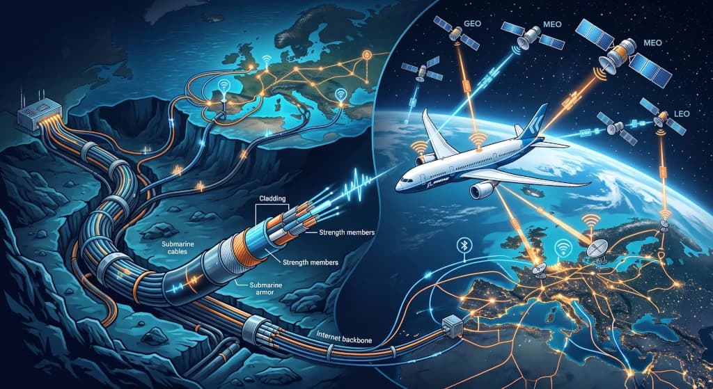
A common misconception is that satellite internet on aircraft operates entirely independent of terrestrial infrastructure. In truth, orbital space is only a single link in the transmission chain. Without the submarine fiber-optic cables that carry more than 95% of all global internet traffic, no aircraft could connect to the wider web.
The physical path of a data signal from the aircraft cabin to the ground follows a precise circuit:
- In-Cabin Segment: Your smartphone connects via onboard Wireless Access Points (WAPs) to the cabin server, which routes the data packet to the aircraft's satellite modem.
- Space Segment (Uplink/Downlink): The antenna mounted atop the fuselage transmits a radio signal to a communications satellite (in LEO or GEO orbit), which amplifies the signal and beams it down to a designated ground station (teleport).
- Terrestrial and Subsea Core: The teleport is directly linked to the terrestrial fiber-optic backbone. If the destination server is on another continent (for instance, messaging a European server while flying over the Pacific), the data travels across high-capacity transoceanic cables—such as MAREA or Dunant—at depths of up to 8,000 meters below sea level.
This entire process—from tapping "send" in your seat to ascending into orbit, traversing the ocean floor, and reaching the destination server—takes merely a fraction of a second. This deep symbiosis between the ocean depths and outer space forms the bedrock of modern aeronautical telematics.
The Evolution of Radio Frequency Bands: From Sluggish L-Band to High-Throughput Ka-Band
The history of aeronautical satellite communications has been a relentless pursuit of bandwidth. For decades, aviation relied on narrow frequency bands sufficient for short cockpit text messages but wholly inadequate for broadband multimedia.
1. L-Band (1–2 GHz): The Resilient Bedrock of Safety
For years, the gold standard for maritime and aviation safety was the Inmarsat (now Viasat) and Iridium satellite networks operating in the L-band. Characterized by longer radio wavelengths, L-band effortlessly penetrates heavy storm clouds, precipitation, and atmospheric turbulence. However, its throughput is modest—measured in hundreds of kilobits per second. As a result, L-band remains exclusively dedicated to mission-critical cockpit communications (Safety Services), where unwavering operational reliability is paramount.
2. Ku-Band (12–18 GHz): The Dawn of Commercial In-Flight Wi-Fi
The true revolution for passenger connectivity began with the deployment of Ku-band systems by providers such as Panasonic Avionics and Anuvu. Operating at higher frequencies, Ku-band delivered streaming speeds of 10–30 Mbps per aircraft. While a major qualitative leap, Ku-band remains vulnerable to rain fade and network bottlenecks when multiple aircraft share a single satellite beam footprint.
3. Ka-Band (26–40 GHz): The Broadband Superhighway in the Skies
The contemporary benchmark for commercial airline fleets is Ka-band, spearheaded by networks like Viasat and Inmarsat Global Xpress. Its higher frequencies enable speeds exceeding 100 Mbps per aircraft, allowing passengers to stream 4K video and participate in online gaming. These networks leverage narrow spot-beam technology, focusing concentrated high-capacity bandwidth over congested flight corridors like spotlights.
Orbital Architecture: Geostationary Giants vs. LEO Constellations
Aviation telecommunications is undergoing its most profound structural shift since the inception of satellite links: the transition between traditional Geostationary Orbit (GEO) satellites and rapidly expanding Low Earth Orbit (LEO) constellations.
GEO Satellites (Geostationary Orbit): Powerful, but Distant
GEO satellites remain stationary relative to Earth, parked above the equator at an altitude of 35,786 kilometers. Their greatest advantage is expansive coverage—just three GEO satellites can provide near-global coverage (excluding the polar caps). However, this immense distance introduces an inescapable physical limitation: latency. The round-trip travel time of radio waves between the aircraft, satellite, and ground averages 500–700 milliseconds, causing noticeable lag in interactive web applications and real-time voice communications.
The LEO Revolution (Low Earth Orbit): Starlink and OneWeb
The arrival of mega-constellations in Low Earth Orbit—such as Starlink Aviation (orbiting at ~550 km) and Eutelsat OneWeb (~1,200 km)—has fundamentally transformed in-flight connectivity:
- Ultra-Low Latency: Drastically reducing orbital distance cuts signal latency down to 20–40 ms, matching terrestrial residential fiber connections.
- True Polar Coverage: LEO satellites fly in near-polar orbits, providing seamless high-speed internet over the Arctic and Antarctic—vital for transpolar flight corridors where GEO satellites fall below the horizon.
- Decentralized Redundancy: Distributed mesh architectures consisting of thousands of smaller satellites ensure that the loss or occlusion of a single satellite causes no service drop; aircraft steer beams seamlessly from one satellite to the next in milliseconds.
Fuselage Technology: Aerodynamics, Phased Arrays, and Thermal Management
Mounting an external satellite antenna on a commercial airliner is a rigorous challenge of materials science and aerospace aerodynamics. The protective radome housing the antenna atop the fuselage must satisfy extreme engineering criteria.
Mechanically Steered Gimbals vs. Electronically Steered Phased Arrays (AESA)
Legacy systems relied on motorized parabolic dishes that physically pivoted within the radome to track satellites during aircraft maneuvers. These assemblies were heavy, added considerable aerodynamic drag, and suffered from mechanical wear on stepper motors and gears.
Modern aviation is rapidly transitioning to Electronically Steered Array (ESA) phased-array antennas. Featuring an ultra-low profile only a few centimeters thick, they eliminate all moving parts. Radio beams are steered purely digitally by microsecond phase-shifting across thousands of tiny solid-state radiating elements, enabling instantaneous, uninterrupted handovers between satellites.
Radomes are engineered from specialized quartz and fiberglass composite laminates that remain completely transparent to high-frequency RF signals while withstanding:
- Airflow friction at speeds exceeding 950 km/h and severe hail impact.
- Extreme thermal gradients ranging from +50°C on desert runways to -60°C at cruising altitude.
- Direct lightning strikes, mitigated through integrated diverter strips that channel static charges safely into the aircraft skin.
The Digital Cockpit Core: ACARS, CPDLC, and Flight Safety
While passenger streaming garners public attention, the most critical application of aviation connectivity remains data telemetry and flight operations safety. The modern airliner is a flying data center, generating gigabytes of diagnostic and environmental telemetry every hour.
Key operational connectivity pillars include:
- ACARS (Aircraft Communications Addressing and Reporting System): A digital datalink protocol transmitting real-time engine health telemetry, fuel burn rates, takeoff weight calculations, and technical advisories straight to the airline's Operations Control Center (OCC).
- CPDLC (Controller-Pilot Data Link Communications): A two-way digital text communication protocol between pilots and air traffic controllers. It replaces scratchy, crackling HF/VHF oceanic voice radio, eliminating phonetic misinterpretations and readback errors during oceanic altitude adjustments.
- Space-Based ADS-B: Aircraft transponders broadcasting GPS position, altitude, and velocity directly to LEO satellite receivers (such as the Aireon network), enabling real-time, global surveillance across oceanic airspace with zero radar blind spots.
Conclusion: An Integrated Digital Future Above the Clouds
Aviation connectivity has evolved from an expensive in-flight perk into the core backbone of global air transportation. The invisible network weaving together subsea ocean floor trenches, orbital constellations, and high-altitude airliners represents an engineering milestone that has permanently erased travel isolation.
By blending LEO mega-constellations, high-throughput GEO satellites, and transoceanic fiber backbones, modern passenger aircraft have become fully integrated nodes within the global cloud architecture. The next time you send a high-altitude snapshot from 36,000 feet, remember: that single beam of data raced through space, dove to the ocean floor, and traversed thousands of kilometers of fiber just to connect your seat to the rest of the world.