HUD and Enhanced Vision in Aviation: Landing in Dense Fog
Introduction: The Blind Wall of Clouds at 200 Feet
Imagine a night approach into a major European hub on a crisp November morning. Outside the windows of a sleek Boeing 787 Dreamliner or Airbus A350, an absolute, impenetrable blanket of white envelops the aircraft. For the past twenty minutes, the jet has been slicing through a dense layer of radiation fog that settled over the river valley, collapsing the Runway Visual Range (RVR) to a critical 150 meters. Inside the passenger cabin, the cabin lights are dimmed as the lead flight attendant's calm voice instructs everyone to fasten seatbelts and stow tray tables. Looking through the passenger windows, travelers cannot even make out the strobes on the raked wingtips. From their perspective, the aircraft is descending into total void at 260 km/h.
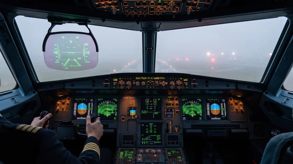
Decades ago, such conditions would have had the flight crew scanning traditional dashboard instruments with extreme focus, darting their eyes back and forth between the attitude indicator and the black windscreen in search of the faintest glow of approach lights. Today, the captain does not even need to look down at the primary flight displays on the main instrument panel. Positioned directly at eye level is a transparent optical glass pane treated with advanced dielectric coatings: the Head-Up Display (HUD). Sharp green flight-guidance symbology glows across the glass, overlaid onto a high-contrast, black-and-white thermal image of the external world supplied by forward-looking infrared sensors. The pilot clearly sees the terrain contours, the runway environment, and individual threshold lights as if the dense fog and aluminum fuselage did not exist at all.
This is neither science fiction nor an experimental military system. It is a proven operational reality in modern commercial aviation, powered by Head-Up Displays (HUD), Enhanced Vision Systems (EVS), Synthetic Vision Systems (SVS), and their fused hybrid—the Combined Vision System (CVS). How do these optoelectronic suites enhance human perception, enabling crews to guide a 250-ton jet to a safe touchdown in conditions of severely degraded visibility?
From Fighter Jets to Commercial Air Transport: What Is a Head-Up Display?
Head-up displays trace their operational roots back to Cold War military fighters. In cockpits such as the F-16 or Mirage, fighter pilots engaged in high-G maneuvers could not afford to divert their gaze downward toward internal instruments to track airspeed, angle of attack, or pitch ladders. In civil air transport, integrating this hardware took decades, largely due to initial unit costs, bulky cathode-ray tube (CRT) projection housings, and rigorous airworthiness certification standards enforced by the FAA and EASA.
The turning point arrived with the development of folded reflective optics and advanced collimated projection systems. A modern commercial HUD is far more than a simple flat-panel screen positioned in the cockpit. It comprises three core architectural assemblies:
- Overhead Projector Unit: A high-luminance optical source—historically high-resolution CRTs, now replaced by solid-state LED arrays or micro-DLP engines—mounted directly into the cockpit ceiling structure above the pilot's head.
- Combiner Glass: A semi-transparent optical plate coated with multilayer dielectric thin films. The combiner reflects a narrow optical wavelength projected from above straight into the pilot's eye box, while transmitting more than 85% of ambient visible light from the real world outside.
- Collimating Optical Assembly: Precision optical elements that focus the projected light rays parallel, effectively projecting the symbology at optical infinity.
This optical collimation provides a critical physiological benefit. When a pilot looks through the combiner out toward the approach lights, their eye lenses do not need to refocus between near and far planes. The primary flight symbology—the pitch ladder, the horizon bar, airspeed tapes, and the target approach speed $V_{\text{APP}}$—does not appear to sit on a piece of glass 30 centimeters from the face. Instead, it appears to float out in the distance, focused on the exact same focal plane as the runway threshold a mile ahead. This eliminates the physiological accommodation time of the human eye (which ranges from 1 to 2 seconds). At an approach speed of 75 m/s, saving that refocusing pause preserves up to 150 meters of spatial tracking during the most critical segment of flight.
The Flight Path Vector (FPV): A Fundamental Shift in Flying Technique
The greatest flight-handling advancement delivered by the HUD is not merely placing the airspeed indicator or altimeter on the windshield; it is the integration of the Flight Path Vector (FPV), often called the "bird" in Airbus operational philosophy. A conventional mechanical attitude indicator shows pitch and bank angles—indicating where the nose of the aircraft is pointing. In the presence of a strong crosswind, however, the aircraft nose may point ten degrees left of the runway centerline to crab into the wind, while the aircraft tracks diagonally across the ground.
The HUD's Flight Path Vector directly resolves this geometric challenge:
- By processing real-time telemetry from Inertial Reference Systems (IRS) and multi-constellation GPS receivers, the flight management computer derives the exact trajectory and momentum vector of the aircraft's center of gravity across three dimensions.
- The FPV is rendered on the combiner as a compact circle equipped with stylized wings and a vertical fin.
- Flying becomes exceptionally intuitive: wherever the pilot places the FPV symbol, that is precisely where the aircraft will fly. If the pilot overlays the FPV directly onto the runway touchdown zone on the combiner glass during approach, the main gear will touch down on that exact spot, regardless of gusting crosswinds or the crab angle needed to track the centerline.
EVS: Thermal Imaging Piercing Clouds and Darkness
A standard HUD displays stroke symbology and vector data. In zero-visibility fog, the pilot still looks at green symbology suspended within a uniform wall of white. The major technical breakthrough came when engineers interfaced the HUD with the Enhanced Vision System (EVS).
At the center of an EVS installation is an externally mounted optoelectronic sensor turret, typically integrated under the radome or along the leading edge of the vertical stabilizer within an aerodynamically streamlined housing. Inside this heated enclosure, protected behind sapphire or germanium crystal lenses, lie focal plane arrays sensitive to multiple infrared wavelengths:
- Long-Wave Infrared (LWIR, 8–14 micrometers): Standard thermal imaging. It captures subtle radiated temperature deltas between concrete runway surfaces, grassy shoulders, drainage swales, and stationary ground obstacles.
- Mid-Wave Infrared (MWIR, 3–5 micrometers): Highly responsive to hot thermal signatures, easily highlighting operating engines on preceding aircraft, heated brake assemblies on rolling jets, and ground vehicle exhaust plumes.
- Short-Wave Infrared (SWIR, 0.9–1.7 micrometers): The core atmospheric penetrator. The microscopic water droplets that constitute radiation fog scatter visible light according to Mie scattering principles, yet remain largely transparent to short-wave infrared spectra. Furthermore, modern airfield LED lighting emits specific spectral profiles that SWIR sensors pick up at distances far beyond the capability of the naked human eye.
Digital signal processors analyze the incoming sensor streams at 60 Hz, filter atmospheric noise, equalize dynamic contrast, and project the calibrated video onto the HUD combiner. The visual result is striking: while looking through the windscreen reveals only dense fog, the HUD displays a sharp, monochrome view of the terrain ahead. The pilot sees runway boundaries, centerline markings, approach lighting towers, and surface obstacles hundreds of meters before they could be spotted with unaided vision.
SVS: Synthetic Virtual Reality in Modern Avionics
While EVS delivers an authentic real-time sensor image, it remains bound by environmental physics: during extreme advection fog with heavy liquid water content or torrential rainfall, infrared transmission drops. To address this limitation, avionics manufacturers engineered the Synthetic Vision System (SVS).
SVS does not use external optical or thermal cameras. It is an onboard 3D rendering engine built upon:
- High-Resolution Terrain Databases (HRTD) detailing global topography down to sub-meter accuracy,
- Comprehensive obstacle databases mapping towers, broadcast antennas, construction cranes, and urban structures,
- Detailed Aerodrome Mapping Databases (AMDB) defining taxiways, holding bays, and runway thresholds,
- Multi-sensor positioning fusing GNSS/SBAS satellite fixes with triple-redundant Inertial Reference Systems (IRS).
Every millisecond, the avionics architecture verifies the aircraft's exact coordinates, altitude, track, and velocity. The graphics processor renders a clean, synthetic 3D model of the terrain ahead. Displayed on the HUD or the primary flight displays, SVS draws terrain contours, elevations, mountain peaks, and runway outlines, often featuring a prospective 3D runway box flanked by an approach corridor—the Highway in the Sky (HITS). The flight crew navigates with clear spatial orientation, knowing the exact position of the surrounding topography even in complete darkness or solid cloud cover.
The Optimal Architecture: Combined Vision Systems (CVS)
On state-of-the-art ultra-long-range business aircraft (such as the Gulfstream G700, Bombardier Global 7500, and Dassault Falcon 8X) and new commercial airliner types, manufacturers have introduced the Combined Vision System (CVS). This integration leverages the strengths of both systems.
CVS merges the real-time sensor imagery of an EVS with the continuous database modeling of an SVS onto a single combiner display. Advanced image-fusion algorithms align the presentations:
- The background terrain, distant peaks, and structural contours are cleanly generated by the SVS synthetic engine.
- The foreground environment—active runway lighting, taxiway layouts, transient ground obstacles, and moving traffic—is provided live by the EVS thermal sensors.
This integration delivers clear Situational Awareness, helping eliminate spatial disorientation—a historical factor in Controlled Flight Into Terrain (CFIT) accidents during final approach and landing phases.
Operational Credits: Lowering Instrument Approach Minima
Deploying HUD and EVS equipment is not simply about situational comfort; it provides tangible operational and economic benefits to commercial carriers.
In standard commercial aviation, instrument approach procedures are categorized by minimum Decision Height (DH) and Runway Visual Range (RVR):
- Category I (CAT I): The baseline precision approach, requiring a Decision Height of at least 200 feet (approximately 60 meters) and an RVR of no less than 550 meters. At the 200-foot minimum, the pilot must establish visual reference with the approach lighting system or runway environment. If the runway is obscured, regulations mandate an immediate go-around.
- Category II / III (CAT II / CAT III): Low-visibility approaches that allow lower decision heights or blind touchdowns. These require certified aircraft systems and specialized airport ground infrastructure (such as dual-frequency instrument landing systems with uninterruptible power supplies, high-intensity centerline lighting, and surface movement radar).
Enhanced Flight Vision System (EFVS) Credits
Regulatory updates from both the FAA and EASA establish operational credits under Enhanced Flight Vision System (EFVS) Operations. Aviation authorities recognize imagery viewed through a certified HUD powered by an EVS sensor as legally equivalent to natural out-the-window visual references.
This regulatory framework provides clear operational advantages:
- Descent Below CAT I Minima: On a standard CAT I approach where normal minimums require level-off at 200 feet, an EFVS-equipped crew may continue their descent down to 100 feet above the touchdown zone elevation based solely on the infrared runway picture on the HUD, even while the forward view through the windscreen remains obscured by fog.
- EFVS to Touchdown: Advanced certification allowances enable qualified flight crews to execute the entire flare, touchdown, and rollout using the HUD/EVS sensor stream without establishing unaided visual contact. The aircraft lands manually on a CAT I runway under meteorological conditions that would otherwise require an automated Autoland CAT IIIb approach at a major hub.
For airlines, this capability significantly reduces costly weather diversions, avoids passenger hotel accommodation fees from displaced flights, and supports regular operations into regional airports that lack expensive ILS CAT III ground installations.
Autoland vs. The HUD-Equipped Pilot: Two Approaches to Low Visibility
Given that modern commercial transports can perform automated landings via Category IIIb/c Autoland systems, why do airlines invest in HUD projectors and forward-looking thermal sensors?
The answer centers on operational flexibility versus infrastructure dependency:
- Autoland Constraints: Executing an automated CAT III landing requires the destination airport to implement strict Low Visibility Procedures (LVP). Airfield ground controllers must increase spacing between aircraft to protect the sensitive ILS localizer and glideslope critical areas from signal distortion, reducing airfield arrival capacity by up to 50%. Autoland systems also carry conservative crosswind limits—often capped between 15 and 20 knots. If heavy fog is accompanied by gusty crosswinds, the autoland system cannot be used.
- HUD and EFVS Flexibility: A manual approach flown via a Head-Up Display allows experienced crews to operate in gusty winds that exceed autopilot certification envelopes. The pilot remains directly in the control loop, maintaining normal airport arrival rates through human adaptability supported by enhanced vision. Furthermore, HUDs provide valuable guidance during Low Visibility Take-Offs (LVTO), where autoland systems do not apply, and maintaining the runway centerline during high-speed acceleration through thick fog is critical.
Engineering Challenges: Aerodynamic Distortion, Sapphire Lenses, and Alignment
Projecting real-time thermal sensor data onto an optical combiner in front of a pilot with sub-millimeter precision presents major optoelectronic design challenges, where minute physical variations require compensation.
The primary hurdle is optical parallax and geometric conformality. The synthetic and thermal imagery displayed on the combiner must match the external physical world 1:1, pixel for pixel. If an electronic runway outline on the HUD is offset by even half a degree relative to the physical concrete hidden in the mist, a manual approach could place the landing gear into the grass beside the runway. Achieving this precision requires calibration algorithms that correct for structural fuselage flex under aerodynamic loads, sensor pod vibration, and subtle head movements within the pilot's viewing eye box.
Materials engineering on the forward sensor housing is equally critical. Specks of atmospheric ice, hail, fine volcanic ash, and acidic rain would quickly pit and erode conventional optical glass at 900 km/h. To withstand these forces, forward EVS sensor windows are manufactured from synthesized single-crystal sapphire or high-grade metallic germanium, materials approaching diamond on the Mohs hardness scale. Embedded micro-grids of transparent Indium Tin Oxide (ITO) provide electrical heating, melting structural ice instantly at cruise altitudes in temperatures down to -60°C to keep the optics clear.
Conclusion: The Era of Transparent Cockpits
The next time you look through a cabin window on approach into thick autumn fog, with the wingtip lights barely visible through the mist, you can trust that the flight crew has a clear picture of the runway environment. Modern avionics has extended the boundaries of human vision on the flight deck.
Through the integration of HUD, EVS, and SVS architectures, flight crews fly with clear digital perception that cuts through heavy fog, night, and precipitation. In this collaborative framework of human skill and aerospace avionics, the nose of the aircraft becomes functionally transparent, guiding the aircraft reliably toward the runway threshold along a focused path of light.