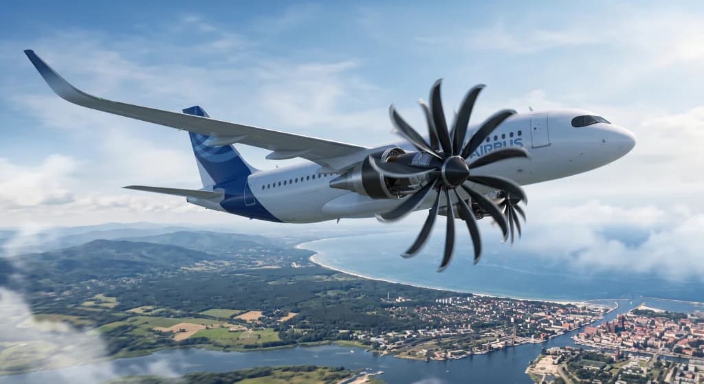
Open Rotor Aircraft Engines: The Future of Commercial Turbines?
Introduction: Bidding Farewell to the Nacelle and the Return of a Radical Concept
For more than half a century, the silhouette of the commercial passenger jet has remained virtually unchanged: a slender fuselage, swept-back wings, and underslung cylindrical nacelles enclosing turbofan engines. Passengers have grown accustomed to smooth engine cowlings with intake diameters that, on the largest airframes, exceed three meters. Yet in aerothermodynamic research centers and on testing benches across the globe, an engineering shift is taking shape that could fundamentally alter this visual profile. Imagine a future narrow-body airliner featuring open, un-ducted carbon-composite blades rotating directly in the freestream, completely devoid of a traditional inlet cowl. This is neither a backward step into the turboprop era nor an aesthetic novelty—this is the Open Rotor engine, referred to technically as an unducted fan (UDF) or propfan.
The concept itself is not entirely new; it initially emerged amid the oil crises of the 1970s, only to be shelved due to plunging oil prices and two persistent operational hurdles: severe acoustic signatures and the metallurgical limitations of the period. Today, driven by stringent decarbonization mandates, the commercial target of Net Zero by 2050, and the imperative to reduce fuel burn by at least 20% compared to contemporary CFM LEAP and Pratt & Whitney PW1000G engines, propulsion engineers have revisited these foundational concepts. Armed with supercomputing capabilities, advanced 3D carbon composites, and planetary reduction gearboxes, industry consortiums such as Safran and GE Aerospace—collaborating on the CFM RISE (Revolutionary Innovation for Sustainable Engines) program—are committing substantial resources to this technology. Could travelers within the next decade board successors to the Airbus A320neo and Boeing 737 MAX families powered by open rotor architectures?
The Physics of Thrust and Efficiency: Why the Nacelle Became a Limitation
To understand why aerospace engineers are moving to remove the engine nacelle, one must consider the aerothermodynamic principles governing air-breathing propulsion. The fundamental metric defining engine efficiency is propulsive efficiency ($\eta_p$). Formulated via the Froude momentum theory, propulsive efficiency is optimized when an engine accelerates an exceptionally large mass of air by a relatively small delta in velocity, rather than expelling a small air mass at extreme velocity.
This aerodynamic relationship drove the historical evolution from low-bypass turbojets to high-bypass turbofans with steadily increasing Bypass Ratios (BPR). First-generation commercial turbofans operated with bypass ratios around 1:1 or 2:1. Contemporary narrow-body engines, such as the CFM LEAP-1A, route bypass air around the core at ratios near 11:1, while the Pratt & Whitney Geared Turbofan reaches approximately 12.5:1. To push the efficiency curve further and achieve bypass ratios of 50:1, 70:1, or 80:1, the fan diameter must expand substantially—to between 3.5 and 4 meters.
At that scale, conventional nacelle designs encounter diminishing returns:
- Nacelle Aerodynamic Drag: The immense wetted surface area of a four-meter cowling generates substantial profile and skin-friction drag at trans-sonic cruise speeds (Mach 0.78–0.80), counteracting the aerodynamic gains achieved by the enlarged fan.
- Structural Weight: The air intake cowl, fan cowl doors, thrust reverser cascades, acoustic attenuation liners, and anti-ice assemblies would add significant parasitic mass, imposing heavy loads on the wing structure and requiring broader airframe reinforcement.
- Under-Wing Ground Clearance: Low-wing commercial airliners have limited clearance between the wing lower surface and the runway pavement. Accommodating a ducted nacelle four meters in diameter would require substantially taller, heavier, and mechanically complex landing gear assemblies.
Omitting the outer nacelle bypasses these physical trade-offs. It enables an expansive fan sweep area while mitigating profile drag and reducing total structural engine weight.
Historical Precedent: The Lessons of the 1980s GE36 UDF
The open rotor concept was previously tested on full-scale flight testbeds. Following the fuel crunches of the 1970s, NASA launched the Advanced Turboprop Project (ATP). By the mid-1980s, General Electric built and flight-tested the experimental GE36 UDF demonstrator, mounting it on a modified Boeing 727 and subsequently on a McDonnell Douglas MD-80 test airframe.
The GE36 was an innovative design for its era, featuring two contra-rotating open rotors driven directly by counter-rotating stages of a low-pressure turbine without an intervening mechanical gearbox. Flight evaluations confirmed a fuel burn reduction of over 30% compared to the low-bypass JT8D turbofans of the period. Nevertheless, the program never entered commercial production.
Three primary factors caused the project to be shelved. By the early 1990s, crude oil prices had declined, softening the commercial demand for capital-intensive engine transitions. Additionally, the computing and materials sciences of the day could not yet manufacture complex, aerodynamically twisted three-dimensional blade profiles. Most decisively, however, the engine produced an unacceptable noise profile.
Because the two contra-rotating blade rows operated in close proximity, the tip vortices and turbulent wakes shed by the front row collided with the leading edges of the rear blades at supersonic relative speeds. This interaction generated a piercing, high-frequency acoustic signature that was clearly audible on the ground and produced noticeable cabin vibration during test flights. The demonstrator could not clear tightening ICAO community noise regulations, prompting manufacturers to pause development.
The CFM RISE Architecture: Engineering Modern Solutions
In 2021, CFM International (a 50/50 joint company between GE Aerospace and Safran Aircraft Engines) launched the RISE (Revolutionary Innovation for Sustainable Engines) program, marking a deliberate return to the open fan architecture using modern propulsion engineering methods.
1. Single-Stage Rotor with Variable-Pitch Stators
A primary mechanical divergence between the historic GE36 and the RISE architecture is the removal of the contra-rotating twin-rotor assembly. The modern design employs an asymmetrical hybrid layout:
- Forward Stage: A single active rotating fan assembly fitted with three-dimensionally profiled, variable-pitch composite blades.
- Aft Stage: A row of non-rotating variable-pitch guide vanes (stators) that adjust their pitch dynamically throughout the flight envelope.
The stationary guide vanes serve to un-swirl the turbulent airflow exiting the rotating forward stage. This converts rotational energy into axial thrust while eliminating the severe blade-on-blade aeroacoustic interference inherent to previous contra-rotating concepts.
2. Composite Aerodynamics: 3D Woven RTM Technology
Open rotor blades operate without the physical shielding of an engine intake. They are directly exposed to potential bird strikes, foreign object debris (FOD), severe hail, and aerodynamic aeroelastic flutter across wide speed ranges.
To meet safety and durability requirements, the blades use 3D woven carbon-fiber composites paired with Resin Transfer Molding (RTM), capped with a bonded titanium leading edge. Instead of bonding flat laminates layer by layer, computer-controlled looms weave the fibers continuously in three dimensions. This produces a lightweight, structurally rigid component with high internal damping characteristics that can withstand severe mechanical impacts. Furthermore, Computational Fluid Dynamics (CFD) modeling allows engineers to give the blades an swept, scimitar profile, delaying the onset of localized trans-sonic shockwaves at the blade tips during high-speed cruise.
3. Mechanical Transmission: High-Power Reduction Gearboxes
An open rotor measuring nearly four meters across cannot rotate at the same rotational speed as the core turbine. Excessive RPM would drive the blade tips well into supersonic regimes ($M > 1.0$), resulting in wave drag and severe acoustic degradation. Conversely, the low-pressure turbine in the engine core achieves optimal thermodynamic efficiency at very high rotational speeds.
To reconcile these requirements, the architecture incorporates an aerospace-grade Power Gearbox (PGB). Utilizing planetary gear arrangements, the gearbox decouples the shafts, allowing the core turbine to spin at peak thermal efficiency (exceeding 10,000 RPM) while reducing the open fan to several hundred RPM. The gearbox must handle tens of megawatts of power with mechanical transfer efficiencies surpassing 99%, supported by dedicated high-volume oil cooling circuits to dissipate heat loads.
Community Noise Mitigation: Controlling the Acoustic Profile
The foremost question confronting international aviation regulators (such as EASA and the FAA) as well as the public is whether open rotor powerplants can operate within strict airport noise envelopes without disturbing communities or degrading cabin comfort.
ICAO noise certifications—notably Annex 16, Chapter 14—impose strict limits on cumulative perceived noise during take-off, sideline monitoring, and approach phases. CFM International targets an acoustic signature for the RISE demonstrator that not only meets Chapter 14 standards but improves upon them by at least 3 to 5 EPNdB (Effective Perceived Noise in Decibels), placing it on par with the quietest modern ducted turbofans.
This reduction is pursued through several aerodynamic design choices:
- Blade-Tip Mach Management ($M_{\text{tip}}$): Through gearbox reduction and variable drive controls, the rotational speed during departure climb-outs and landing approaches is kept well below sonic thresholds, mitigating strong shockwave formation.
- Variable-Pitch Blade Management: Adjusting the blade pitch angles allows the system to match the exact aerodynamic requirements of each flight phase, optimizing airflow attach points and preventing boundary-layer separation during throttle changes.
- Stator-Rotor Aerodynamic Spacing: The axial distance between the rotating blades and the static guide vanes is engineered using psychoacoustic modeling to ensure harmonic sound frequencies attenuate rather than reinforce one another.
Airframe Integration: Structural and Aerodynamic Positioning
Applying an open rotor to a commercial airframe demands fundamental reconsiderations of transport aircraft geometry. Fitting a four-meter rotor involves different trade-offs depending on its placement.
1. Under-Wing Mounting
Mounting the powerplants beneath the wings remains the industry preference for weight distribution, wing bending relief in flight, direct load transfers, and line-maintenance access. However, given an open rotor's large diameter, adapting a low-wing airliner requires distinct design modifications:
- Transitioning to a high-wing airframe configuration (similar to regional military airlifters), which alters interior cabin structural frames and main gear storage wells, or...
- Designing extended landing gear struts to elevate the wing structure several meters above the tarmac, introducing significant structural weight penalties and ground-handling complexities.
2. Rear-Fuselage Pylon Mounting
An alternative airframe layout positions the engines on structural pylons at the rear of the fuselage, paired with a T-tail or U-tail empennage, drawing from past airframes like the MD-80 or VC-10.
This layout leaves the wings aerodynamically clean and avoids ground clearance issues. Furthermore, the fuselage and empennage structures serve as acoustic barriers, reflecting a portion of the propulsion noise upward away from communities on the ground. However, this design requires structural reinforcement of the aft pressure bulkhead and shifts the operating empty center of gravity rearward, complicating center-of-gravity balance calculations during varied passenger loading conditions.
3. Uncontained Blade Failure Mitigation
Conventional turbofan cowlings contain a ballistic containment ring made of woven Kevlar and titanium. If a fan blade breaks off due to foreign object ingestion or fatigue, the ring retains the fragments inside the nacelle, protecting the passenger cabin, control runs, and wings from high-energy shrapnel.
An open rotor system operates without an outer containment structure. If a composite blade were to detach under high centrifugal load, it would be thrown outward along the rotor plane. Consequently, airframe certification requires specialized composite armor reinforcement along the fuselage within the rotor burst trajectory, or positioning the engine aft of the passenger cabin and primary flight control linkages.
Alternative Energy Carriers: SAF and Hydrogen Integration
The open rotor concept is being engineered to accommodate alternative aviation fuel paths. The engine core is intended to support 100% drop-in Sustainable Aviation Fuels (SAF) derived from hydroprocessed esters, synthetic paraffinic kerosenes, and Power-to-Liquid e-fuels.
Additionally, the architecture aligns with liquid hydrogen ($H_2$) combustion research, including evaluations within programs such as Airbus ZEROe. Hydrogen combustion yields primarily water vapor and demands unique thermal core conditions. The high bypass volume of the open rotor configuration provides extensive ambient airflow to support heat exchangers while maintaining low thermal $NO_x$ emissions. Pairing a 20% aerodynamic propulsive gain with clean-burning hydrogen represents a key technical pathway toward net-zero commercial operations.
Development Timeline and Flight Demonstrations
Progressing from a technology demonstrator to a certified transport-category engine follows an extensive developmental and regulatory timetable:
- 2026–2027: Rigorous ground testing of full-scale engine core components and open fan assemblies across manufacturer test cells.
- Circa 2028: Commencement of flight-test campaigns using a specialized Airbus A380 (MSN001) flight testbed. The open rotor powerplant will be mounted to a modified pylon on the upper forward fuselage of the aircraft to evaluate freestream aerodynamics, acoustics, and flutter characteristics across varied flight levels.
- Mid-2030s: Projected commercial service entry. If engineering milestones and certification criteria are met, open rotor powerplants could form the baseline propulsion options for clean-sheet airframes replacing current single-aisle fleets.
Conclusion: The Changing Aesthetics of Commercial Aviation
Open rotor propulsion illustrates how aerospace concepts can be successfully revisited as materials and manufacturing methods advance. What proved excessively loud and mechanically limited in the 1980s has been revitalized by modern aerodynamic design, precision planetary reduction systems, and composite weaving.
For airline passengers, watching an un-ducted, scimitar-shaped composite rotor turn outside a cabin window would represent a departure from familiar configurations. Yet commercial aviation history is defined by iterative transitions focused on efficiency and capability. Should the open rotor validate its efficiency and acoustic targets over the coming test cycles, the next generation of single-aisle airliners will leave traditional cowlings behind to fly with greater fuel efficiency and reduced emissions.