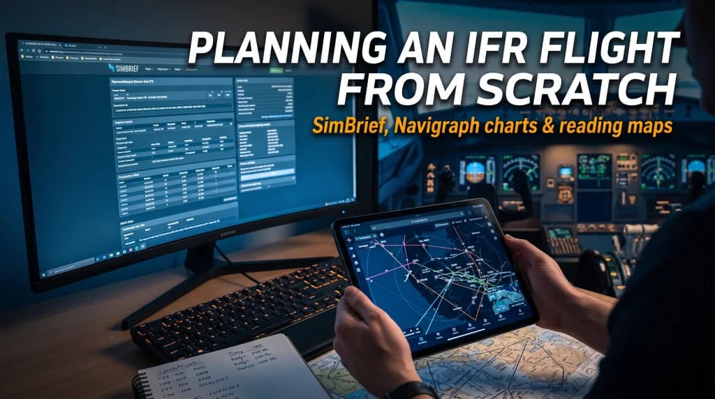
IFR Flight Planning from Scratch: SimBrief, Navigraph Charts, and Map Reading
Introduction: Leaving "Stick-and-Rudder" Casual Flying Behind
For every flight simulation enthusiast, a defining turning point inevitably arrives: merely launching the simulator, setting up on the active runway, and tracking direct GPS straight-lines no longer satisfies the itch for realism. The genuine allure of aviation does not begin when the throttles are slammed into the TOGA detent on the runway; it starts hours earlier at the virtual dispatcher's desk. Operating under Instrument Flight Rules (IFR) is a disciplined discipline governed by standardized procedures, performance numbers, altitude restrictions, and structured airways, where every phase is methodically scripted and the margin for error is razor-thin.
Today’s flight simulation ecosystem provides operational tools that virtual aviators a decade ago could barely envision. Integrating the dispatch platform SimBrief with Navigraph Charts grants home pilots access to the very resources utilized daily by commercial airline Operations Control Centers (OCC). This comprehensive guide walks you step-by-step through professional IFR flight planning: from establishing operational criteria and decoding a detailed Operational Flight Plan (OFP) to interpreting certified Jeppesen instrument charts.
The Foundation of Flight Planning: The AIRAC Cycle and Navdata Alignment
Before launching a dispatch session and plotting navigation fixes, you must understand the bedrock of modern aeronautical navigation: the AIRAC (Aeronautical Information Regulation And Control) cycle. Airspace is not a static geometry. High-altitude airways are frequently realigned, navigation intersections (fixes) are renamed or decommissioned, and radio navigation facilities (VORs, ILS localizers) undergo regular recalibrations and frequency reassessments.
The International Civil Aviation Organization (ICAO) mandates a strict 28-day update cycle for aeronautical databases. If your desktop flight simulator (such as Microsoft Flight Simulator or X-Plane) runs an outdated navdata cycle while SimBrief computes a route based on current airspace design, your aircraft's Flight Management Computer (FMC/MCDU) will reject waypoint formats or fail to pull up assigned departure procedures. Navigraph unifies and updates the navigation databases across your core simulator, study-level airliner addons (Fenix, PMDG, ToLiss), and SimBrief, ensuring total database synchronicity across every waypoint, airway, and radio frequency.
SimBrief in Practice: Generating the Operational Flight Plan (OFP)
SimBrief is an advanced, freely available dispatch platform that models commercial airline planning systems like Sabre and Lido. To construct a flight plan, log in and navigate to Dispatch > Create New Flight.
Core Flight Setup Parameters
- Flight Identification: Input your operating airline ICAO code and flight number (e.g., LOT3801 / LO3801).
- Airport Pair: Specify the departure and destination ICAO identifiers. SimBrief cross-references live METAR observations and TAF forecasts to suggest appropriate active runways.
- Alternate Airports: Designating a suitable diversion field is a regulatory mandate under IFR. SimBrief computes the reserve fuel burn required for an aborted approach, transit to the alternate, and an additional 30-minute holding pattern.
- Airframe Profile: Select a verified airframe profile matching your addon. Variations in Dry Operating Weight (DOW) between different equipment configurations can shift baseline mass by hundreds of kilograms, directly altering fuel burn figures and climb gradients.
- Cost Index (CI): A fundamental airline operational parameter reflecting the ratio between direct time-related operating costs and fuel expenses. A setting of
CI = 0optimizes exclusively for minimal fuel burn at lower airspeeds, whereas higher values (e.g.,CI = 80on legacy aircraft) command the FMC to fly higher cruise speeds at the expense of fuel economy.
Anatomy of the OFP: Isolating Key Operational Data
Selecting Generate Flight produces an extensive multi-page Operational Flight Plan (OFP), typically rendered in standard LIDO format. While it includes extensive en-route details, the primary figures on the briefing page demand priority attention:
- BLOCK FUEL: The total gross fuel quantity required aboard prior to engine start. This includes Trip Fuel, Taxi allowance, Alternate burn, Contingency reserves, and the legally required Final Reserve (typically 30 or 45 minutes of holding fuel).
- ZFW (Zero Fuel Weight): The total mass of the aircraft including crew, passengers, and payload, entirely excluding usable fuel. This figure is programmed directly into the FMC/MCDU initialization pages (INIT B).
- TOW (Takeoff Weight): Projected gross weight at brake release. This value must strictly remain beneath the certified Maximum Takeoff Weight (MTOW).
- CRZ ALT (Cruise Altitude): The calculated cruise flight level optimized for current winds aloft and gross weight (e.g., FL350, representing 35,000 feet on standard altimeter setting 1013.25 hPa / 29.92 inHg).
The Routing String: Decoding Airway Syntax
To an untrained eye, the text string populated in the Route field looks like random code. It is, in fact, an orderly sequence of airways, transitions, and airspace intersections. Consider the following routing:
EPGD EVINA7C EVINA M857 BAPSE T710 DENKO DENK2P EPKK
Decoded component by component:
- EPGD: Origin airport ICAO identifier (Gdańsk Lech Wałęsa Airport).
- EVINA7C: The assigned Standard Instrument Departure (SID) procedure, structuring the climb-out from the departure runway to the airway entry point at EVINA.
- EVINA: The terminal waypoint of the SID, joining the upper en-route airway structure.
- M857: Designated upper airway. In the FMC flight plan page, this airway is entered under the left VIA column, with exit waypoint BAPSE entered on the right under TO.
- BAPSE: The waypoint marking the transition off airway M857 onto the subsequent trunk route.
- T710: The interconnecting airway linking waypoint BAPSE with DENKO.
- DENK2P: The assigned Standard Terminal Arrival Route (STAR), routing the aircraft from transition point DENKO into the terminal maneuvering area of Kraków-Balice (EPKK).
Navigraph Charts: Reading Instrument Procedures
With the flight plan imported into the avionics suite and linked within Navigraph Charts (which renders standardized Jeppesen terminal charts), the crew must brief four essential chart categories.
1. Airport Diagram (Chart 10-9)
The top-down aerodrome layout chart governs all surface movements from pushback to the runway threshold, and subsequently from runway turnoff to the parking stand:
- Taxiways: Alphanumerically labeled pavement paths (e.g., Taxiway Alpha, Bravo, Mike). Ground control assigns routing clearances accordingly (e.g., "Taxi to holding point Runway 29 via Alpha and Bravo").
- Runway Holding Points: Clearly designated double solid and dashed lines painted across taxiways and marked on charts. Crossing these hold lines without explicit clearance to enter or cross the active runway constitutes a severe runway incursion.
- Airport Elevation: The highest point of an airport's usable landing surfaces measured in feet above Mean Sea Level (MSL), vital for cross-checking barometric altimeter calibration.
2. Standard Instrument Departure (SID)
The SID chart designs the departure path to ensure separation from high terrain, obstacles, and arriving airspace flows:
- Minimum Climb Gradient: Detailed in chart notes or profile footers (e.g., "Minimum climb of 5.0% until passing 3000 ft"). The airframe must possess the physical climb performance to clear the obstacle environment at its actual takeoff weight and ambient air temperature.
- Altitude Restrictions: Depicted directly adjacent to waypoints. A figure underlined (e.g., FL100) mandates crossing at or above that altitude. An overline specifies at or below, while bars both above and below require crossing at that exact target flight level.
- Speed Limits: Annotations such as
MAX 220 KTimpose mandatory indicated airspeed ceilings to preserve turn radius integrity within tight procedural tracks.
3. Standard Terminal Arrival Route (STAR)
The STAR is the mirror image of a SID at the end of the cruise phase. Originating at the final en-route airway fix, it channels descending airliners into the terminal environment toward the Initial Approach Fix (IAF):
- Energy Management and Descent Profiles (Top of Descent): The STAR demands structured deceleration and altitude step-downs. Modern airliners exhibit high aerodynamic efficiency; dumping excess airspeed while simultaneously maintaining a steep rate of descent is challenging without speedbrake deployment.
- Transition Level Identification: The altitude or flight level where altimeters are transitioned from standard reference pressure (1013.25 hPa / 29.92 inHg) back to local altimeter setting (QNH).
4. Instrument Approach Chart (e.g., ILS Runway 25)
This is the primary instrument reference during final approach in marginal weather. It provides the essential localizer and glideslope parameters for precision guidance:
- Navigational Aid Frequency and Identifier: Found in the upper briefing strip, detailing the localizer and glide path frequency (e.g.,
109.90 MHz) alongside its three-letter Morse code identifier (e.g.,IKR). - Inbound Approach Course: The magnetic final approach track (e.g.,
253°), dialed into the COURSE (CRS) window on the mode control panel (MCP/FCU). - Glide Slope Intercept Altitude: The level flight platform altitude (e.g.,
3000 ft) where the aircraft intercepts the electronic glide path beam, traditionally fixed on a 3.0-degree descent angle. - Decision Altitude (DA) / Decision Height (DH): Located in the landing minimums matrix at the base of the plate (e.g.,
DA 320 ft (200 ft)). This represents the lowest altitude to which a descent may continue without visual reference to the runway environment (approach lighting or threshold markings). If visual acquisition has not occurred by DA, an immediate go-around (Missed Approach) via the TOGA switches is mandatory.
Fuel and Speed Management: Golden Rules of Cockpit Discipline
Disciplined IFR planning prevents two of the most frequent errors in flight simulation: fuel exhaustion short of destination and unstable approaches driven by excessive kinetic energy.
When initializing the flight management computer, verify that the calculated reserve fuel corresponds to the FINAL RESERVE value generated on your SimBrief briefing. During final descent, the FMC computes target approach speed $V_{\text{APP}}$, derived from gross landing weight and the reference speed $V_{\text{REF}}$ for the chosen landing flap detent (e.g., $V_{\text{APP}} = V_{\text{REF}} + 5\text{ kt}$). Understanding how these reference values correlate with target speeds on approach charts equips the pilot to manage challenging conditions, like gusty crosswinds and localized shear, with confidence.
Conclusion: From Preparation to the Touchdown Zone
Structured IFR planning with SimBrief and Navigraph fundamentally reframes the flight simulation experience. You step beyond casual flying into the role of a pilot-in-command, coordinating a complex navigational system within tightly structured airspace.
Investing fifteen minutes in briefing terminal charts, auditing climb restrictions, and double-checking fuel reserves pays dividends when it matters most: breaking out of the cloud deck at 250 feet in torrential rain, right on the extended centerline and established on the glideslope. That technical satisfaction is the hallmark of serious flight simulation.