ILS CAT IIIb System: How Modern Airliners Land in Zero Visibility
Introduction
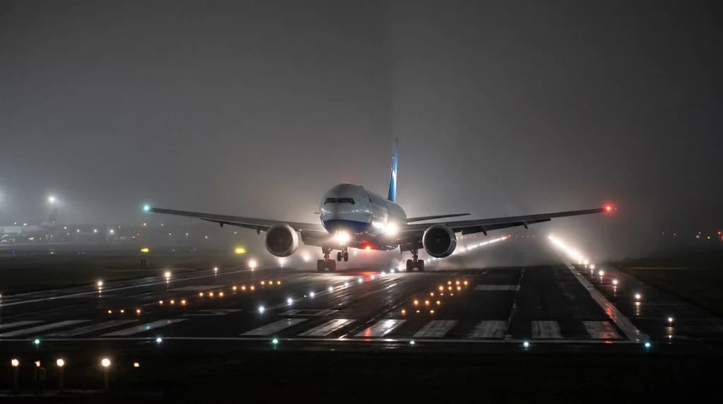
For a passenger gazing out the window of a modern jetliner, touching down in dense autumn fog feels like descending into an endless vat of milk. The descent continues, the turbofans hum with a muted, steady drone, and outside there is absolute emptiness—no city lights, no horizon, not even the strobes on the wingtips. Barely tens of meters above the terrain, the fog remains unbroken. Passengers instinctively tense against their armrests, braced for the roar of engines spooling up for an immediate missed approach. Instead, a crisp thud echoes through the cabin as tires contact concrete, the roar of thrust reversers erupts, and the aircraft decelerates smoothly down a runway neither the flight crew nor the passengers could see with the naked eye moments before.
This is neither reckless daring nor blind intuition from the cockpit. It represents the pinnacle of avionics engineering, radio wave physics, and operational discipline: the Category IIIb Instrument Landing System (ILS CAT IIIb). This technology revolutionized commercial aviation by stripping severe low-visibility weather of its power to paralyze flight operations. How can a two-hundred-ton aircraft traveling in excess of 250 km/h intercept a narrow ribbon of concrete purely through electromagnetic signals and flight management algorithms?
The Evolution of Precision: From Bonfires to ILS Categories
Early bad-weather aviation relied on crude techniques: burning bonfires along landing strips, listening for engine noise from ground observation posts, and firing visual flare bursts. The rapid maturation of radio engineering across the 1930s and 1940s laid the foundation for the contemporary ILS. The International Civil Aviation Organization (ICAO) classified instrument approaches into rigorous categories based on two interdependent metrics: Decision Height (DH) and Runway Visual Range (RVR).
Decision Height is the precise vertical point along the glide path—measured via radio altimeter—where the flight crew must establish visual reference with specific runway markings or approach lighting to continue manually to touchdown. If those visual references are not acquired by this threshold, executing an immediate Go-Around is mandatory.
Precision approach tiers are categorized as follows:
- Category I (CAT I): The baseline precision approach. Requires a DH of no less than 200 feet (approx. 60 meters) and an RVR of no less than 550 meters (or 800 meters general visibility).
- Category II (CAT II): Intermediate precision. DH drops to between 100 and 200 feet (30–60 meters), with an RVR minimum of 300 meters.
- Category IIIa (CAT IIIa): Breaking the 100-foot floor. DH sits below 100 feet (often 50 feet), with an RVR of at least 175–200 meters. Demands automated guidance down to touchdown, though the pilot must acquire visual cues moments before the wheels touch.
- Category IIIb (CAT IIIb): True "blind" landing capability. Decision Height is under 50 feet (15 meters) or entirely absent (No DH). The required RVR drops to a minimal 50 to 75 meters—a visibility bubble so constrained that a flight crew taxiing clear of the runway cannot see the adjacent taxiway centerlines.
- Category IIIc (CAT IIIc): A theoretical standard—zero feet DH and zero meters RVR (zero visibility). While modern avionics can perform this touchdown profile, CAT IIIc is not operationally certified worldwide for practical reasons: emergency rescue services cannot locate an off-runway incident in zero visibility, nor can an aircraft safely taxi to its arrival gate.
The Invisible Funnel: How Ground-Based ILS Transmitters Work
An ILS relies neither on orbital GPS constellations nor onboard thermal imaging sensors. Its architectural backbone consists of ground-based high-frequency directional antenna arrays (VHF and UHF) projecting an electromagnetic funnel through the terminal airspace. This structure comprises two distinct, independent signal arrays: the Localizer (LLZ) and the Glide Path (GP).
1. The Localizer (LLZ): Runway Centerline Guidance
Positioned beyond the stop end of the active runway, the localizer antenna array transmits within the 108.10–111.95 MHz VHF band. Its tracking precision stems from amplitude modulation. The antenna array projects two overlapping radio lobe patterns modulated at distinct audio frequencies:
- The left sector is modulated at 90 Hz.
- The right sector is modulated at 150 Hz.
When an aircraft tracks down the physical centerline of the runway, its onboard receiver registers identical modulation depths from both signals (Difference in Depth of Modulation – DDM = 0). If the airframe drifts even a fraction of a degree off course, one frequency dominates, allowing the flight management computer to compute the angular displacement and immediately correct control surfaces.
2. The Glide Path (GP): Vertical Path Tracking
The glide path antenna mast sits offset from the runway edge, abreast of the touchdown zone approximately 300 meters past the threshold. Operating in the UHF band (329.15–335.00 MHz), it utilizes the same modulation principle as the localizer, applied across the vertical plane:
- The upper lobe is modulated at 90 Hz.
- The lower lobe is modulated at 150 Hz.
The intersection of these two signals forms an inclined electronic plane, traditionally set to a 3-degree descent angle (Glide Slope). This slope provides an optimal sink rate of roughly 700–800 feet per minute at normal approach speeds ($V_{\text{APP}}$), keeping the aircraft clear of surrounding terrain and structures.
Cockpit Redundancy: Autoland and Fail-Operational Architecture
Legal dispatch into CAT IIIb minimums demands far more than a clean ground signal. A wide-body airliner—such as a Boeing 777, 787, or Airbus A350—operates as a fully redundant computing complex during these approaches. Certification rules require the automatic landing system (Autoland) to meet strict Fail-Operational standards.
This means no Single Point of Failure can compromise the approach. Should a flight guidance computer fail 30 meters above the runway, the crew cannot be abruptly forced to take manual control in dense fog. CAT IIIb aircraft incorporate triplex or quadruplex independent computing channels:
- Triplex Autopilot Architecture: Three independent flight guidance computers (designated Autopilot L, C, R on Boeing types; paired PRIM and SEC computers on Airbus types) process inputs in parallel from separate sensor suites, ILS receivers, and Inertial Reference Systems (IRS).
- Voting Logic: The computers cross-compare calculations continuously. If one computer deviates from the consensus of the other two, it is instantly voted out and isolated without transient flight control deflections.
- Segregated Electrical and Hydraulic Power: Should an engine-driven generator drop offline, high-speed static inverters, main ship batteries, or the APU generator take over critical avionics buses in milliseconds to prevent computer reboots.
The Flare and Rollout: Automated Touchdown Dynamics
Guiding an airliner down to the runway threshold is only the first phase. The most demanding interval is the flare maneuver and keeping the aircraft pinned to the centerline rollout. In CAT IIIb conditions, human sensory perception is too slow; automated subsystems retain command.
1. The Flare Mode and Radio Altimeters
Barometric altimeters are unsuitable near the surface due to inherent pressure lag and local atmospheric variance. CAT IIIb operations rely strictly on downward-looking Radio Altimeters (RA), which calculate true height above ground with centimeter-level precision.
At approximately 50 feet (15 meters) above the runway, the Flight Mode Annunciator (FMA) engages the FLARE mode. The autopilot applies gentle nose-up command, lifting pitch by 2–3 degrees to bleed off the vertical descent rate from 4 m/s to a safe 0.5 m/s. Concurrently, the autothrottles retard toward IDLE, spooling down thrust immediately before tire contact.
2. Centerline Rollout: The Key CAT IIIb Capability
This is where CAT IIIa and CAT IIIb diverge. In CAT IIIa, the autopilot completes the flare, but once the tires make contact, the pilot must steer the rollout visually using the rudder pedals. In CAT IIIb conditions with 75-meter visibility, distinguishing the runway edges at 250 km/h is impossible. The system requires an active ROLLOUT mode.
Weight-on-wheels sensors confirm ground contact upon touchdown, yet the autopilot remains engaged. Using the localizer signal along the runway length, the flight guidance system commands the nosewheel steering and applies differential braking. This keeps the multi-ton airframe tracking the painted centerline until it slows to a safe taxi speed or turns off onto an exit taxiway.
Ground Procedures: Low Visibility Procedures (LVP)
A CAT IIIb approach requires a coordinated airport-wide protocol. When visibility drops below 600–800 meters, Air Traffic Control activates Low Visibility Procedures (LVP), transforming the aerodrome into a strictly controlled operating zone.
Key LVP operational restrictions include:
- ILS Critical and Sensitive Areas: No aircraft or ground vehicle may approach the localizer or glide path arrays during CAT IIIb operations. A waiting wide-body like a Boeing 777 held near the runway could reflect or refract the radio signals, creating fatal guidance distortions for an approaching aircraft. Holding points for taxiing traffic are pushed back to greater distances from the runway.
- Extended In-Trail Separation: Controllers expand final approach spacing from the typical 3–5 nautical miles up to 8, 10, or 12 nautical miles. This guarantees that a landing aircraft fully vacates the active runway and clears the sensitive signal area before the next arrival crosses decision height.
- High-Intensity Airfield Lighting: Centerline lights embedded flush with the asphalt every 15 meters and taxiway centerline green lead-offs illuminate at maximum intensity to give crews directional cues.
- Advanced Surface Movement Guidance (A-SMGCS): Because tower controllers cannot visually monitor the movement area, ground operations are tracked using surface movement radar, multilateration transponder systems, and automated runway stop bars.
The Flight Crew: Managers of Automated Systems
The prevalence of CAT IIIb capabilities does not make the flight crew passive observers. On the contrary, performing an autoland in low visibility presents peak mental workload, shifting the pilots' role from manual manipulation to high-intensity systems monitoring.
The captain's hands hover millimeters from the control column or sidestick, with feet resting against the rudder pedals and thumbs poised over the autopilot disconnect switches. Both pilots perform disciplined instrument scans:
- Cross-checking the Flight Mode Annunciator (FMA) to verify that LOC, G/S, FLARE, and ROLLOUT modes arm and engage at their designated altitudes.
- Monitoring tracking tolerances: a localizer deviation exceeding one dot below 200 feet mandates an immediate Go-Around.
- Strict standard callouts: at 100 feet, the Pilot Monitoring (PM) calls "One hundred". If all parameters are within bounds, the Pilot Flying (PF) confirms with "Continue". Upon touchdown, the callout follows: "Rollout, Reverse Green".
Pilots do not trust the automated flight computers blindly; they monitor the approach to catch any system discrepancy instantly, ready to firewall the throttles to TOGA thrust and climb away into the clear air above.
Conclusion: Engineering Over the Elements
An ILS CAT IIIb landing demonstrates how modern aerospace engineering manages extreme atmospheric environments. Dense fog, which once paralyzed transportation networks for days on end, has been transformed into a manageable operational condition.
The next time your aircraft descends into a blanket of fog, hear the tone of the engines settle, and feel the aircraft track straight onto the runway in near-zero visibility, you are experiencing the integration of precision radio guidance, multi-channel avionics, and disciplined aircrew procedures working together to deliver a safe arrival.